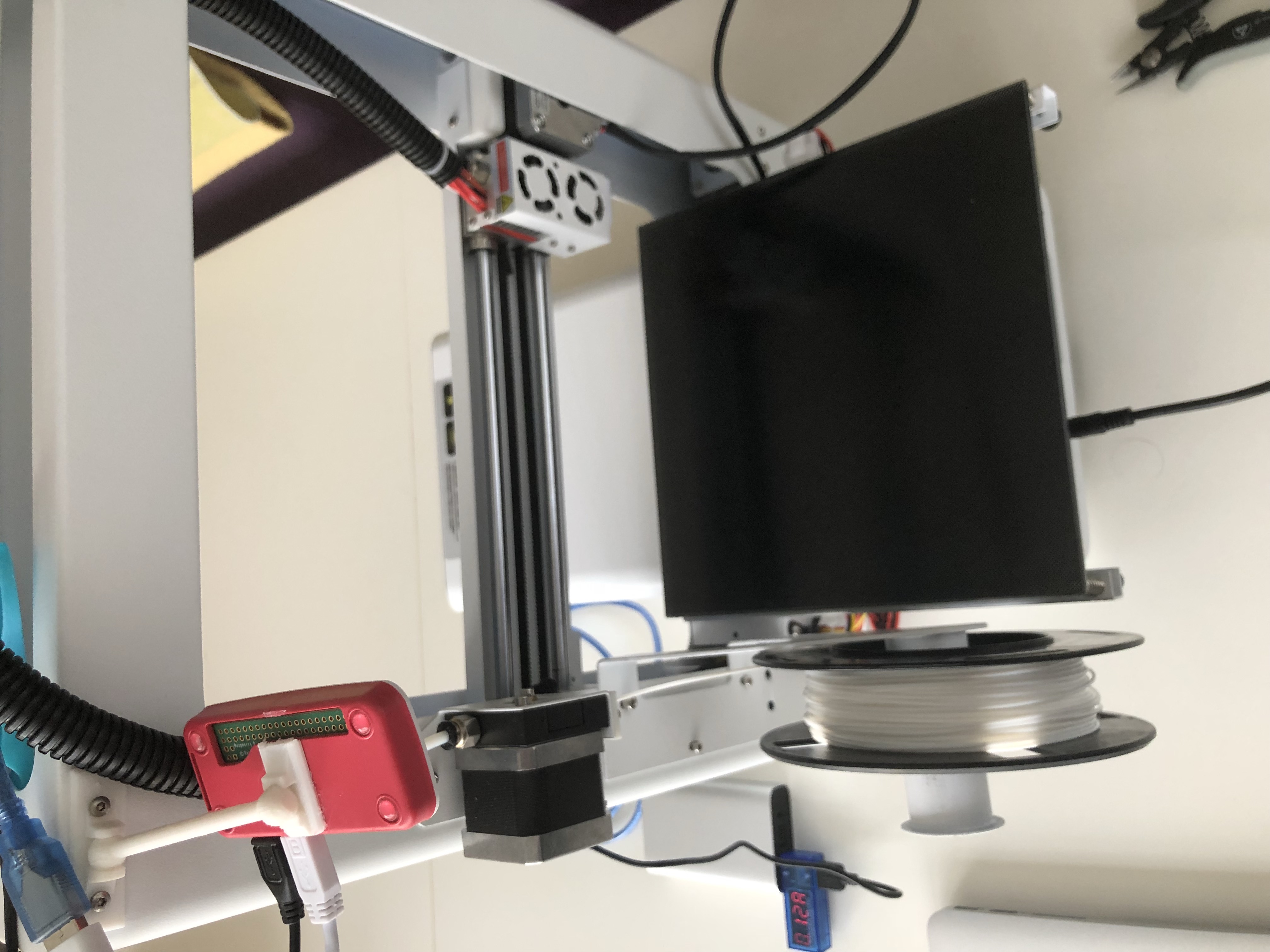

Now, we need four things to power the PI and communicate: 3.3v power, which the display header gives us, Ground, which the display header gives us, TX, and RX, which.the display header gives us. The PI will report it's underpowered, since the 5v side isn't being supplied, BUT, it behaves fine in my testing, and since the 5v exists to feed the 3.3v regulator, we're probably fine. It turns out, we can power the PI directly, feeding it 3.3v.
If your LCD is dead and you're never, ever going back, you could cut the display cable (shudder!) and use it. See for a good breakdown of connectors and sizing. If your LCD works or you ever intend to replace it, a JST kit in like SPH-001T in either P0.5L or P0.6L depending on whether or not you have a V1 or V2 (V2 uses the narrower pin connection). To do this, you'll need a Raspberry Pi Zero W (if you're going to attempt this with a B, A, or anything else, go ahead and wire up a power supply. On this particular board, I had no LCD, so why not take the opportunity to make an all-in-one?

While I acknowledge that the Raspberry Pi Zero W isn't recommended for octoprint, that's primarily because of slowdowns when streaming video. Soldering to the debug pads on a V2 is a complex operation for someone as shaky as I am. Now, those with nimble fingers and usb-electron-robo-soldering irons will easily repair the port, sometimes even soldering on a different size/type. In the words of my 2 year old daughter, it "badded" the connector. Why? Because the person in question had discovered that if one steps on the usb connector, it will transmit the force upward, outward, and other-wards. This began as an answer to the question "Is there any other way to hook up Octoprint that doesn't involve USB?"


 0 kommentar(er)
